|
||||
| PiroSTOP System | ||||
|
||||


|
IDAXA PiroSTOP Control Panelis modular, distributed intelligence device. Modular architecture allows any additions at any time.
Because of the distributed intelligence the decisions and the information storage happen in more, than one units of the center. This also gives the advantage of easy expandability and, on the other hand, the fact that in the case of large-scale objects the decision-making level can be installed close to the detectors without risking the operation of the whole fire alarm system in the case of injury of the cable network.
IDAXA PiroSTOP Control Panelhas two-level hierarchy. The lower level is for detector level devices, (HI1, BI12KR8, OI1), and the upper is for control level devices (VEZ, KKE, JFE+GIK).
The task of detector level devices is to collect information from the detectors, the input devices and to make controls.
The task of control devices is managing detector devices, information processing, decision making, information storage, and to ensure user management.
In the figure may be seen the connection of the the single units to the fire alarm system.
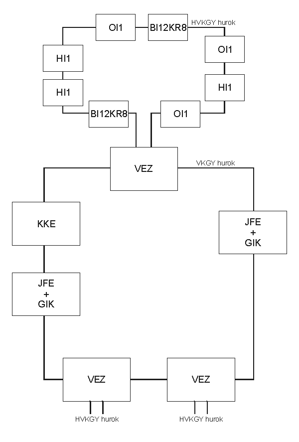
Detector lever devices are linked to HVKGY loops, the control level devices are linked to VKGY loops. The different levels of the two-level hierarchy are connected through the VEZ devices. Every VEZ device has its own HVKGY loop.
Both VKGY and HVKGY are loops of twisted pair lines with RS485 communication. Every device communicates continuously with the neighbor one. In this contact one device is the "master", the other one is the "slave". Communication always initiates from the "master" side, but the information flow is two-way. The structure of the VKGY and HVKGY looops ensures, that every device max be reached in the case of single line gap.
Every device is connected to the VKGY and HVKGY loops via the Intelligent Interface Unit (IIE), which watches the communication. If the communication of a unit connected to the loops is not satisfactory, (e.g. it does not respond to the messages), IIE disconnects the device from the loop, which remains in operation, but the information of the defective unit will not get the user (exept the error message).
The devices have 8-bit address in every loop, so the total number of devices in every loop is 256.
It follows from the topology, that every device may have individual power supply unit, but more devices may have common housing with common power supply.
The OI1 and KKE units have separate house and and power supply. The VEZ, HI1 and BI12KR8 units may be built into common house with common power supply. JFE units are installed in the house of GIK computers.
|
Main features:
|